Semi-Rigid Diaphragm Analysis Considerations
The slab meshing is treated similar to analysis results. When the results of an analysis are deleted, the slab mesh is cleared to be re-built during the next solution. When a solution results file is saved, the meshed elements will be included in that file.
- This topic is only applicable for RISAFloor ES/RISA-3D combined models that have semi-rigid diaphragms. For information on semi-rigid considerations for RISA-3D only models see the Diaphragms topic.
- The program uses the finite element analysis, along with cracking factors (columns, beams and slabs) to come up with the stiffness of each element and the system as a whole. ACI 318-14 Sections 8.11.3, 8.11.4 and 8.11.5 (ACI 318-11 Sections 13.7.3, 13.7.4 and 13.7.5) provide ways to estimate the stiffness of individual elements in the equivalent frame method. These provisions are not used in the program.
Mesh Considerations
Mesh Size
The global mesh size for the slab can be input on the Solution tab of the Model Settings. As a smaller mesh size is more accurate, the mesh size can get too small. The smaller mesh size will lead to longer solution time and more memory usage.
Graphical Display of the Slab Mesh
By default, the plate elements associated with the slab are not visible to the user. The mesh can be turned on using the setting on the Model View Settings - Diaphragms tab. Listed under the Wireframe selection, the Show Mesh check box will turn the display of the slab mesh on or off.
Note
- The display of the mesh is only available when there are active analysis results.
Point and Line Constraints for the Slab Mesh
Point constraints are the locations within the slab that require connectivity to the meshed plate elements. The program will automatically generate point constraints at the following locations:
1. Support points which include: joints along a wall panel and column joints (see Column Meshing for full description).
2. Beams points which include: the start, end and intermediate joints along the beam.
3. Any nodes that land in the plane of the semi-rigid diaphragm that have Joint Loads applied to them.
Note:
- The P-Delta Leaning Column effect is not considered for RISAFloor gravity columns in a combined RISAFloor/RISA-3D model.
Beam Connectivity to Mesh
Beams drawn on a Two-Way slab are meshed directly to the surrounding plates. The picture below shows the center-line of the beam is meshed to the plates.
Column Meshing
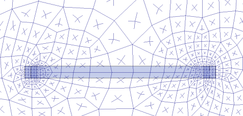
The top of the column will be submeshed and connected to the surrounding plates with rigid links in a 12" x 12" square. This approach is more accurate than modeling the column connection at only one node. When only one node is used the slab will have a higher peak moment and higher deflection at that one point. Instead the rigid links create a rigid region over the top of the column that approximate the stiffness of the column attachment to the slab. The size of the rigid links will not change based on the column dimensions as this is only approximate. In most cases there will be 4 plates inside the rigid links.

The column node will connect to the slab via the additional diagonal rigid links. After the slab is meshed, additional diagonal rigid links are drawn to connect the column node to the square rigid links (shown below). The column node has rotational and translational support so there will be vertical and rotational constraint at the column location.
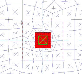
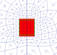
In most cases, the column node will land inside the 2x2 plate mesh in the same location as a plate corner. However, in certain edge and corner situations, as well as beam intersections, the column node will not align with the plate corners.
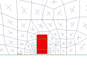
|
|
| Edge Column | Beam Intersecting a Column |
-
The slab connection to the column rigid link top depends on the model merge tolerance being within the 12"x12" rigid link square. If the model's merge tolerance has been set too high in the Model Settings, the slab mesh may not connect to the columns as seen by the deflected shape and slab forces. If this occurs, reduce the merge tolerance back to the default 0.12" and the slab mesh will attach to the column.
Slab Stiffness Considerations
Selecting a Deflection Method of I Cracked/Elastic in the Model Settings controls the stiffness reduction based on the Icr factor in the Slabs spreadsheet
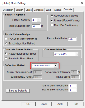
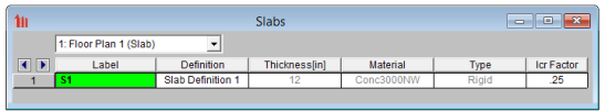
The Icr factor default is set to 0.25 per ACI 318-14 Section 6.6.3.1.1 (ACI 318-11 Section 10.10.4.1). You can modify this factor with any value between zero and 1.0 by typing in this field. The Icr factor adjusts the stiffness of the plate elements comprising the slab by altering the thickness during solution. This adjusted thickness does not, however, affect design values (reinforcement calculations).
Service Checkbox
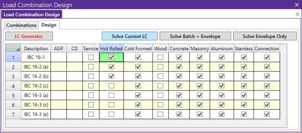
The commentary in ACI 318-14, Section 6.6.3.1.1 (ACI 318-11 Section 10.10.4.1) recommends a 1.43 factor to be applied to the cracked moment of inertia for all service loads. The program applies this factor to all Load Combinations that have the Service checkbox turned on, as long as the Use Cracked Slabs is selected in the Model Settings. This results in an effective default slab moment of inertia of (0.25)*(1.43)*Ig = 0.3575*Ig
Note: The Long Term Deflection will also give the cracking analysis for the Service Load Combinations in the graphical display, spreadsheet results and Detail Report.